

简介
顶点着色是一种将颜色信息直接应用于网格顶点的简便方法。这种方式常用于生成式 3D 模型的构建,例如
本教程将介绍一种快速的解决方案,将顶点着色的网格转换为 UV 映射和纹理化的网格。内容包括 简短版 (帮助您迅速获取结果),以及 详细版 (提供深入的操作指导)。
简短版
安装
pip install git+https://github.com/dylanebert/InstantTexture
用法
以下代码将顶点着色的 .obj 网格转换为 UV 映射的纹理 .glb 网格,并将其保存为 output.glb 文件。
from instant_texture import Converterinput_mesh_path = "https://raw.githubusercontent.com/dylanebert/InstantTexture/refs/heads/main/examples/chair.obj"
converter = Converter()converter.convert(input_mesh_path)
可视化输出的网格。
import trimeshmesh = trimesh.load("output.glb")
mesh.show()
就是这样!
如果需要更详细的步骤,可以继续阅读下面的内容。
详细版
首先安装以下依赖项:
pip install numpy trimesh xatlas opencv-python pillow httpx
导入依赖项。
import cv2
import numpy as np
import trimesh
import xatlas
from PIL import Image, ImageFilter
加载带有顶点颜色的输入网格。该文件应为 .obj 格式,位于 input_mesh_path 。
如果是本地文件,使用 trimesh.load() 而不是 trimesh.load_remote() 。
mesh = trimesh.load_remote(input_mesh_path)mesh.show()
查看网格的顶点颜色。
如果失败,请确保网格是有效的 .obj 文件,并且带有顶点颜色。
vertex_colors = mesh.visual.vertex_colors
使用 xatlas 生成 UV 映射。
这是整个处理过程中的最耗时部分。
vmapping, indices, uvs = xatlas.parametrize(mesh.vertices, mesh.faces)
将顶点和顶点颜色重新映射到 UV 映射。
vertices = mesh.vertices[vmapping]vertex_colors = vertex_colors[vmapping]mesh.vertices = verticesmesh.faces = indices
定义所需的纹理大小。
构造一个纹理缓冲区,通过 upscale_factor 以创建更高质量的纹理。
texture_size = 1024upscale_factor = 2
buffer_size = texture_size * upscale_factortexture_buffer = np.zeros((buffer_size, buffer_size, 4), dtype=np.uint8)
使用质心插值填充 UV 映射网格的纹理。
v0 、v1 和 v2 定义的三角形内的点 p 的插值颜色,分别对应颜色 c0 、c1 和 c2 。p 是否位于由顶点 v0 、v1 和 v2 定义的三角形内。uv0 , uv1 , uv2 ) 和颜色 (c0 , c1 , c2 )。# Barycentric interpolation
def barycentric_interpolate(v0, v1, v2, c0, c1, c2, p): v0v1 = v1 - v0 v0v2 = v2 - v0 v0p = p - v0 d00 = np.dot(v0v1, v0v1) d01 = np.dot(v0v1, v0v2) d11 = np.dot(v0v2, v0v2) d20 = np.dot(v0p, v0v1) d21 = np.dot(v0p, v0v2) denom = d00 * d11 - d01 * d01if abs(denom) 1e-8:
return (c0 + c1 + c2) / 3 v = (d11 * d20 - d01 * d21) / denom w = (d00 * d21 - d01 * d20) / denomu = 1.0 - v - w
u = np.clip(u, 0, 1)
v = np.clip(v, 0, 1)
w = np.clip(w, 0, 1) interpolate_color = u * c0 + v * c1 + w * c2return np.clip(interpolate_color, 0, 255)
# Point-in-Triangle test
def is_point_in_triangle(p, v0, v1, v2):
def sign(p1, p2, p3):
return (p1[0] - p3[0])*(p2[1] - p3[1]) - (p2[0] - p3[0])*(p1[1] - p3[1]) d1 = sign(p, v0, v1) d2 = sign(p, v1, v2) d3 = sign(p, v2, v0)has_neg = (d1 0) or (d2 0) or (d3 0)
has_pos = (d1 > 0) or (d2 > 0) or (d3 > 0)return not (has_neg and has_pos)
# Texture-filling loop
for face in mesh.faces: uv0, uv1, uv2 = uvs[face] c0, c1, c2 = vertex_colors[face]uv0 = (uv0 *(buffer_size - 1)).astype(int)
uv1 = (uv1 *(buffer_size - 1)).astype(int)
uv2 = (uv2 *(buffer_size - 1)).astype(int)min_x = max(int(np.floor(min(uv0[0], uv1[0], uv2[0]))), 0)
max_x = min(int(np.ceil(max(uv0[0], uv1[0], uv2[0]))), buffer_size - 1)
min_y = max(int(np.floor(min(uv0[1], uv1[1], uv2[1]))), 0)
max_y = min(int(np.ceil(max(uv0[1], uv1[1], uv2[1]))), buffer_size - 1)for y in range(min_y, max_y + 1):
for x in range(min_x, max_x + 1):
p = np.array([x + 0.5, y + 0.5])
if is_point_in_triangle(p, uv0, uv1, uv2): color = barycentric_interpolate(uv0, uv1, uv2, c0, c1, c2, p)texture_buffer[y, x] = np.clip(color, 0, 255).astype(
np.uint8 )
让我们可视化一下目前的纹理效果。
from IPython.display import displayimage_texture = Image.fromarray(texture_buffer)display(image_texture)
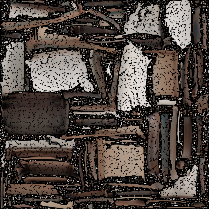
正如我们所看到的,纹理有很多空洞。
为了解决这个问题,我们将结合四种技术:
texture_size 。# Inpaintingimage_bgra = texture_buffer.copy()mask = (image_bgra[:, :, 3] == 0).astype(np.uint8)* 255
image_bgr = cv2.cvtColor(image_bgra, cv2.COLOR_BGRA2BGR)inpainted_bgr = cv2.inpaint(image_bgr, mask, inpaintRadius=3, flags=cv2.INPAINT_TELEA
)inpainted_bgra = cv2.cvtColor(inpainted_bgr, cv2.COLOR_BGR2BGRA)texture_buffer = inpainted_bgra[::-1]
image_texture = Image.fromarray(texture_buffer)# Median filter
image_texture = image_texture.filter(ImageFilter.MedianFilter(size=3))# Gaussian blur
image_texture = image_texture.filter(ImageFilter.GaussianBlur(radius=1))# Downsample
image_texture = image_texture.resize((texture_size, texture_size), Image.LANCZOS)# Display the final texture
display(image_texture)
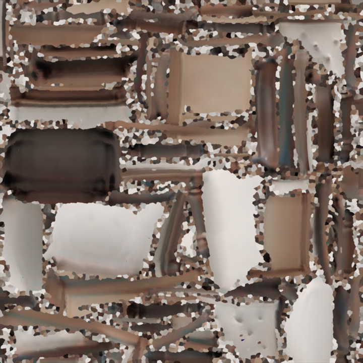
正如我们所看到的,纹理现在变得更加平滑,并且没有空洞。
可以通过更高级的技术或手动纹理编辑进一步改进。
最后,我们可以构建一个带有生成的 UV 坐标和纹理的新网格。
material = trimesh.visual.material.PBRMaterial(
baseColorFactor=[1.0, 1.0, 1.0, 1.0], baseColorTexture=image_texture,metallicFactor=0.0,
roughnessFactor=1.0,)visuals = trimesh.visual.TextureVisuals(uv=uvs, material=material)mesh.visual = visualsmesh.show()
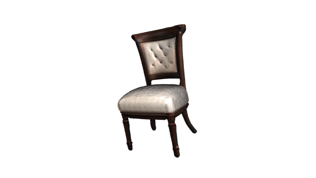
就这样!网格已进行 UV 映射并贴上纹理。
在本地运行时,您可以通过调用 mesh.export("output.glb") 来导出它。
局限性
正如您所看到的,网格仍然存在许多小的伪影。
UV 地图和纹理的质量与生产级网格的标准仍有较大差距。
然而,如果您正在寻找一种快速解决方案,将顶点着色网格映射到 UV 映射网格,这种方法可能会对您有所帮助。
结论
本教程介绍了如何将顶点着色网格转换为 UV 映射的纹理网格。
如果您有任何问题或反馈,请随时在
感谢您的阅读!
原文链接:
https://hf.co/blog/vertex-colored-to-textured-mesh 原文作者: Dylan Ebert
译者: cheninwang
